Pages

Saturday, June 10, 2023

Jdy-31 SPP bt module

 This is about JDY-31, an SPP bluetooth module. 

This is cheap bluetooth module compared to   HC-06 which is claimed to be pin-compatible.

My Experience

I bought this because this is cheap. And serve its purpose. Just to replace USB-to-TTL module, then I can connect my device using bluetooth instead of wired one. This especially important to isolate the device (providing electrical isolation).

Unfortunately, I spent 3 days to configure this module until I found the way.

Why

I need to configure this device because it baudrates doesn't match the device. The module's baud is default 9600 bps. So I need to change it. Besides, it would be cool to change the broadcast name.

The result

I am successfully configures the module. here what is need to be considered:

  1. The default pairing pin is 1234, in case you doesn't found the manual. Yes, this module is sold without packaging.
  2. Check the voltage. In case you forgot, UART begins with high logic, start bit is low. So RX of BT is connected with TX of device, and logic is high.
  3. This module is slave device. Means it cannot initiate connection. 
  4. The configuration uses AT command. So you need to connect with other device to configure. I use USB-to-TTL module to configure using PC.
  5. AT command is case sensitive.
  6. AT command must ends with CRLF or 0x0D0A.
  7. JDY-31 only respond to right command. So entering AT will not respond. Comparing other modules which may responds OK.
  8. The command needs to sent using burst mode. Means the AT prefix until CRLF must not have significant delay. I don't know the exact amount. 
    1. Realtime mode: the character is sent as you type. Typing 'A' will be sent immediately. Many terminal application use this mode.
    2. Burst mode: Sent only done when user press send button. Terraterm use 'broadcast' for this mode.
  9. The AT command only works if not connected. Unfortunately, no pin for indicating the connected state. Only LED which is blinked. When connected, obviously the command will be sent plainly to the connected master.
  10. No difference between unpaired or paired.
So that is the conclusion.

Commands I use
Here some command I use:
  • AT+VERSION
    • connected: will send AT+VERSION to master device.
    • unconnected: will respond +VERSION=JDY-31-V1.35,Bluetooth V3.0
  • AT+BAUD. Setting baud rate to 115200 bps: AT+BAUD8
    • connected: will send entire command to master device.
    • unconnected: will respond +OK
    • query command AT+BAUD, reponse +BAUD=8
    • the default is BAUD4 for 9600 bps.
    • Note: the actual baud is not changed until the device is restarted. You can confirm this by sending AT+VERSION. If the modules respond, means the baud is not changed. Try to change the terminal baud rate setting. And see if it respond. Then unpower the module and re power it. Try sending AT command again. This also means the setting is kept even the module is unpowered. No need initialization.
  • AT+DISC: disconnect the bluetooth's serial connection. This only AT command valid when connected.
    • connected: respond +DISC=SUCCESS and broke transmit connection. Actually it kept connected, only cannot transmit, only receive.
    • unconnected or broke transmit: no response.
    • To normalize this state, use soft reset AT+RESET. Or hardware reset by unpower-repowering module. Module will respond +OK for soft reset. The connected device will respond with connection lost.

Wednesday, July 28, 2010

how to transfer 2 byte data

Sometimes you want to send 2 byte data or more. But we all know that many transfer medium like serial, I2C, CAN bus, bluetooth, etc; only allows use 1 byte data transfer only. So how to send integer value into byte medium? One way is converting into a sequence of character. Another way is splitting the data per bytes. For example, sending integer16 into byteHi and byteLo. It may easy if using assembly languages.
This time I'll show you how to send integer data from microcontroller to PC. I'm using C language in the microcontroller, and C# in the PC.
The key of these processes are 16 bit to 8 bit converter.

On the PC, using C#
memory mapping
//using System.Runtime.InteropServices
struct unionStruct {
   [FieldOffset(0)]
   public short bigVal;
   [FieldOffset(0)]
   public byte smallLow;
   [FieldOffset(1)]
   public byte smallHi;
}

Basically, we create struct. But somehow, we make one field is overlapped in the memory. This is the splitting work. As shown on the picture, bigVal is overlapped with the memory of smallLow and smallHi. In the other words, when we put a value in the smallLow, we can access it from smallLow or from bigVal. When we put 0x12 in the smallLow, it's same like we put 0x0012 in the bigVal. When we put 0x34 in the smallHi, then, in the bigVal will be read 0x3400. So if we put 0x1234 in the bigVal, then we can read the low byte in the smallLow which has the value of 0x34. And also we can read the high byte in the smallHi which has the value of 0x12. It has the same principles on C language.

On the microcontroller, using C
typedef struct {
memory mapping
   unsigned char lo;
   unsigned char hi;
}hilo_t;

typedef union {
   unsigned int besar;
   hilo_t  kecil;
}hilo_ut;

In the C language, we can't control the field offset. So we can create a structure that has 2 byte field. And then we put the structure in the union to make it overlapped with 2 byte memory.

How it works?
To send data, make sure the sequence is same for the microcntroller and the PC.This to avoid misunderstanding between PC and microcontroller of how to put the high byte and the low byte.
  1. Splitting 16-bit data to send to PC.
    hilo_ut byteInterface; //declaration
    byteInterface.besar = data16;   //put 16-bit data
    send(byteInterface.kecil.lo);      //send low byte first
    send(byteInterface.kecil.hi);      //send high byte
  2. Assembly two 8-bit data into 16-bit data in the PC
    unionStruct byteInterface = new byteInterface();  //declaration
    byteInterface.smallLow = read();   //read low byte first because microcontroller sends low byte first
    byteInterface.smallHi = read();      //read high byte
    short needee = byteInterface.bigVal; //read the 16-bit data
  3. Splitting 16-bit data to send to microcontroller.
    unionStruct byteInterface = new byteInterface();  //declaration
    byteInterface.bigVal = dataBig;   //put the 16-bit value
    send(byteInterface.smallLow);      //send low byte
    send(byteInterface.smallHi);      //send high byte
  4. Assembly two 8-bit data into 16-bit data from the PC
    hilo_ut byteInterface; //declaration
    byteInterface.kecil.lo = read();   //read low byte first
    byteInterface.kecil.hi = read();      //read high byte
    unsigned int nedee = byteInterface.besar;
That is how the easy way.

Tuesday, July 20, 2010

how to trap errors in firmware

Programming a microcontroller sometimes makes you frustrated. Its because it has errors which we don't know where. So these is a little example:

-----------
for(;;)
{
   valueA = functionA();
   valueB = functionB();
   valueC = functionC();
}
------------ but my microcontroller seems not work??
Lets create a trap using leds attached on portA
--------------
//for(;;)
//{ //just make sure this piece of code run only one time
  portA = 1; 
  valueA = functionA();
  portA = 2;
  valueB = functionB();
  portA = 3;
  valueC = functionC();
  portA = 4;
//}
-------------
now look at leds, :
  • value = 4; it means all functions is working.
  • value = 2; it means functionA is never done, is must have some infinite loop like while (true value), or for(i=0;i>2;i--) but i value never goes below 2, etc. Now you know that the errors is inside functionA, you may delete the trap and create new trap just inside functionA
Another way is create some monitor to evaluate value. For example:
Suppose you have UART function working properly and called SendUsart(char data)
---------

for(;;)
{
   SendUsart('A'); SendUsart('0');
   valueA = functionA();
   SendUsart('B'); SendUsart(valueA);
   valueB = functionB();
   SendUsart('C'); SendUsart(valueB);
   valueC = functionC();
   SendUsart('D'); SendUsart(valueC);
   _delay_ms(500); //just to make your hyperterminal not flooded :D
}---------
now lets look at your hyperterminal:
....A0B2C3D5A0B2C3D5A0B2C3D5...
just look at the repeated value. Let suppose you have :
functionA(){
  return 50;
}
functionB(){
  return (valueA + 1);
}
functionC(){ 
  return (valueB + 1);
}
and the reading....
B2 : because on functionA you put 50, it will send 2 (ascii value of 2 is 50 decimal)
C3 : inside functionB, you add valueA with 1, the result is 51 (ascii : 3)
D5 : inside functionC, you add valueB with 1, the result must be 52 (ascii: 4), but in the reading is 53 (ascii value : 5). So the valueB must be changed somewhere. Usually from interrupt routine. You may check the routine.

so that is how using trap and monitor for finding bug inside firmware. Experienced programmer know where to put traps and monitor in error-prone routine.

Saturday, July 17, 2010

removing many items from list

Let's take a look a screenshoot first :

Lets suppose you have a list, and you want to delete selected list.
For the first time, I am using foreach, but it throws an exception. Yes of course, item count will change after removing. So the foreach constraint will changed while looping. So it can't use foreach. It must use loop.
for(int i = 0; i<mList.Count; i++)
  It's wrong because m.List.Count will change after deletion. You must create buffer to accomodate this.
int mCount = mList.Count;
for(int i = 0; i < mCount; i++)
mList.RemoveAt(table.Rows[i].index);

It's also remove unwanted items. Its because after deletion, index also change. For example, when you remove index 1 and then index 3, what actually happens is you delete index 1, and then index 2 become index 1, and soon. When you remove index 3, actually you remove the item who has index of 4 before deletion loop. Its now become index 3 and this who will be deleted. Because the index before deleted items never change, you can reverse the loop:
 int mCount = mList.Count - 1;
for(int i = mCount; i >=0; i--)
{
mList.RemoveAt( table.Rows[i].index);
}

Thursday, May 27, 2010

sine array generator


Sometimes we want to create sine wave from our microcontroller project. And it need arrays of constants to fed to PWM generator. And you don't know what constants to be filled to.

Well, I have same problems too. So I calculate sine wave formula and put it into a software to make it simpler.

If you found some bug, please let me know by posting comment in this blog

requirements : minimum Net Framework 2.0

Sine Array Generator
md5: 4D9FF7189BE49D6C376F0E112AFC6A8E

note : of course i have a tool for calculating md5 in here

Saturday, October 25, 2008

how to trap "delete" key event in C#

"delete" key is a special, it has different function from other key. That's why we can't use ordinary key down / key press event. For example, I have richTextBox called "rtbInput", pictureBox called "picLine" and I want to update line number whenever user delete some text. This is my code to do that :

private void rtbInput_PreviewKeyDown(object sender, PreviewKeyDownEventArgs e)
{
            if(e.KeyCode == Keys.Delete )                 
                LineNumber.DrawLineNumber(picLine.CreateGraphics(), rtbInput, picLine); 
    //this is my function to draw line number
}
note that function named "rtbInput_PreviewKeyDown" means I attached this handler to previewKeyDown event of the richTextBox.

Wednesday, October 15, 2008

manually create table of figures

You may want to include table of figures or table of tables but you cannot do automatically. This steps will show how to add table of figures (TOF for short).
  1. block the caption of your picture, on "insert" tab, click "bookmark". A bookmark dialog will shows up.
  2. add the bookmark name. Make sure to insert the name that represent the picture. Example : name "pic2_1" for picture 2.1, "pic2_11" for picture 2.11, "pic2_1_1" for picture 2.1.1
  3. click "add". this will insert your bookmark to the bookmark table ( until now, I can't find the way view that table). If you found "add" disabled, it means you insert wrong character for bookmark name
  4. set your tabs. right-click on your documents and select "paragraphs....", click "tabs". The "tabs" dialog will shown.
  5. add your tab stop. Insert position, set the alignment and leader, click set. Do this for each tab-stops. for example mine use 2,75 cm, left, leader : 1, and 15,5 cm, right, leader : 2. second tab is used for entering "......" between name and page number and to ensure the page number are "right aligned".
  6. you can insert page number for your table entry by clicking "cross-reference" at "insert" tab. This will show reference dialog. select "reference type" as bookmark and "insert reference to" as page number (you want to insert page number). Select bookmark and click insert. note that you must insert page number at the page where the bookmark located. if you're not, the number will not shown up.
  7. don't edit the page number manually because it will updated before printing and makes your editing useless.
  8. you can update manually by right-clicking near page number and select "update field".
This is my TOF entry for example, look for tab stops :


easy creating table of contents

If you writing a experiment report or something,
maybe you want to include table of contents (or TOC for short) for you report. I'l show you how..... First thing first, after everything is set, you must insert page number, don't forget that. This is my example. After do that, follow all steps below :
  1. block the word you want to use as entry word on TOC. Like below....
  2. on "references" tab, click "Add text"
  3. select the level you want. For example, in picture above, I'm using "chapter I" as level 1 in table of contents, "1.Subchapter" as level 2, "a. subchapter" as level 3.
  4. If you found the word you've selected changed. You can change manually. Or, you can modify "Heading 1 default" right-click on "heading1" at "home" tab. This is the default format for level 1 heading (you can change later after adding TOC).
  5. after you have entered all entry word, try to view your document map.
  6. If you see unwanted entry on your document map, just click on your map to jump on tha entry. Block that word, on "references" tab, click "Add text". You will found that corresponding level is cheked. Simple check "do not show in table of content". This will remove from entry. just check on your document map.
  7. If all set, jump to page you want the TOC to be inserted. On "references" tab, click "table of contents" and select "automatic table".
  8. After you've edit some pages, you may want to update your TOC. you can do this by clicking "update", it usually located at the top of your TOC.
  9. you can change the format of your table entry, but do this after you've update your entire table.
  10. You can change heading for your TOC by clicking "table of contents" on "references" tab and selecting "insert table of contents". this will show "TOC" dialog. Click "modify" button. Select the level you want, click "modify". On "style based on" you can select from heading if you've change the default heading or just simply edit the format.
thats all. Now you have a TOC.

how to insert page number with different format?

sometimes you want to insert different page number format, for example on several pages with format : i, ii, iii, and several pages with number like: 1,2,3. You can do that by following steps below :
  1. put your cursor at the end of page.
  2. select "page layout" tab, click "breaks", select "next page".
  3. on next page, double click header (and footer).
  4. unmark "link to previous". this make your header (and footer) not same as previous page.
  5. thus, changing page number in this page doesn't change page number in previous page .

Friday, September 05, 2008

How to create custom animation brush in the gimp

This time, I want to show how to create simple custom animation brush in the GIMP.
  1. Create new canvas, mine is 133x80 px. If you want the brush have independent color. Create canvas with RGB mode, fill with transparency. If you want the color of the brush depend from the brush dialog, use Grayscale mode, fill with white (not foreground or background).


  2. Create your image, maybe you want to create to another layer so you can edit later. Or, open example image as new layer. This image originally from deviant art, a photoshop brush. Then I convert into .png with some converter.
  3. Merge down this image's layer (right click - merge down).
  4. Create new layer. Like first layer, fill with transparency if you want color-independent brush. Or fill with white for color-dependent.

  5. Like step 3, merge down this last layer.

  6. The result is layer with image with white background.
  7. Repeat step 4 and 5 until all your image is inserted.
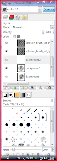
  8. Save as GIMP animation brush (.gih). Of course you can save as .xcf for later editing. This image right is just example (my work). Because mine has 7 image total (7 layer). I'm using ranks = 7 so that all 7 images will show when brush is used. Random means the images will show randomly as you move the brush.
  9. Is done! Just copy your new created brush to Brush folder and it's ready.
  10. Time to test your new brush. Click refresh in brush's dialog and your new brush will shows up.

This is my brush.

How to create custom static brush in the gimp

I'll show you how to create custom static brush for use with the GIMP.
  1. Create new canvas, mine use 375x50 px. If you want a brush that have own color, use RGB mode and fill the canvas with transparency. If you want a brush that have color depend from brush dialog, use grayscale mode and fill the canvas with white (not foreground or background) like image below

  2. Create your image, maybe you want to create to another layer so you can edit later. Or, open example image as new layer. This image originally from deviant art, a photoshop brush. Then I convert into .png with some converter.

  3. Save this image as GIMP brush (.gbr). When the dialog shows up, select flatten image and press export.
  4. Voila! and you're done. Just copy your new brush to brush folder and click refresh brush dialog.
  5. Your new brush will shown. It's time to test your new brush.

This is my resulting brush.